
01
Introduction & Interpretation
Understand what 3MF analysis can tell you, what it cannot prove, and how engineering findings should be interpreted.
Start with 3MF Analysis →Moksha3D Engineering Knowledge Base
A practical engineering guide to understanding 3MF analysis, interpreting geometry findings, investigating mesh faults, choosing repair tools and validating the result before manufacturing.
3MF vs STL
A 3MF file can package geometry together with units, materials, metadata and manufacturing information, while STL primarily describes a triangulated surface mesh.
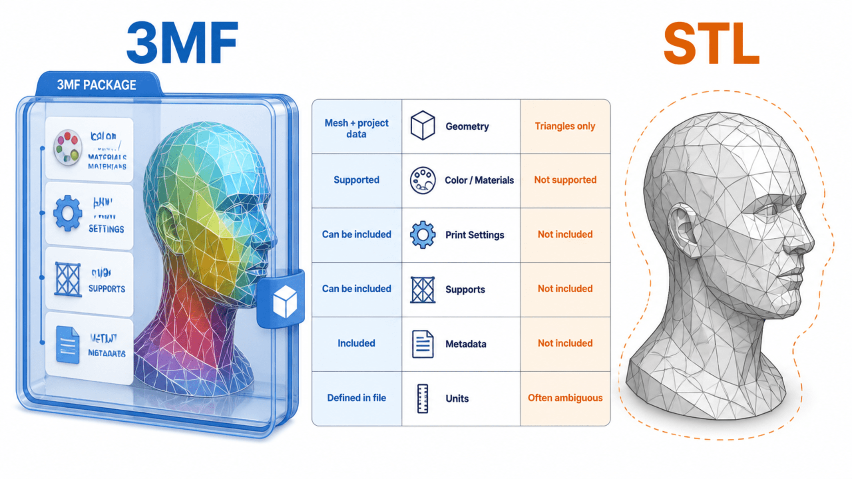
3MF can preserve additional manufacturing information within the file package. The exact contents depend on how the 3MF was created and which extensions or application-specific data are included.
Inside a 3MF Package
A 3MF file is a ZIP-based package that can carry more than the model mesh. Depending on how the file was created, it may also contain materials, colours, units, metadata, textures and manufacturing information used by compatible software.
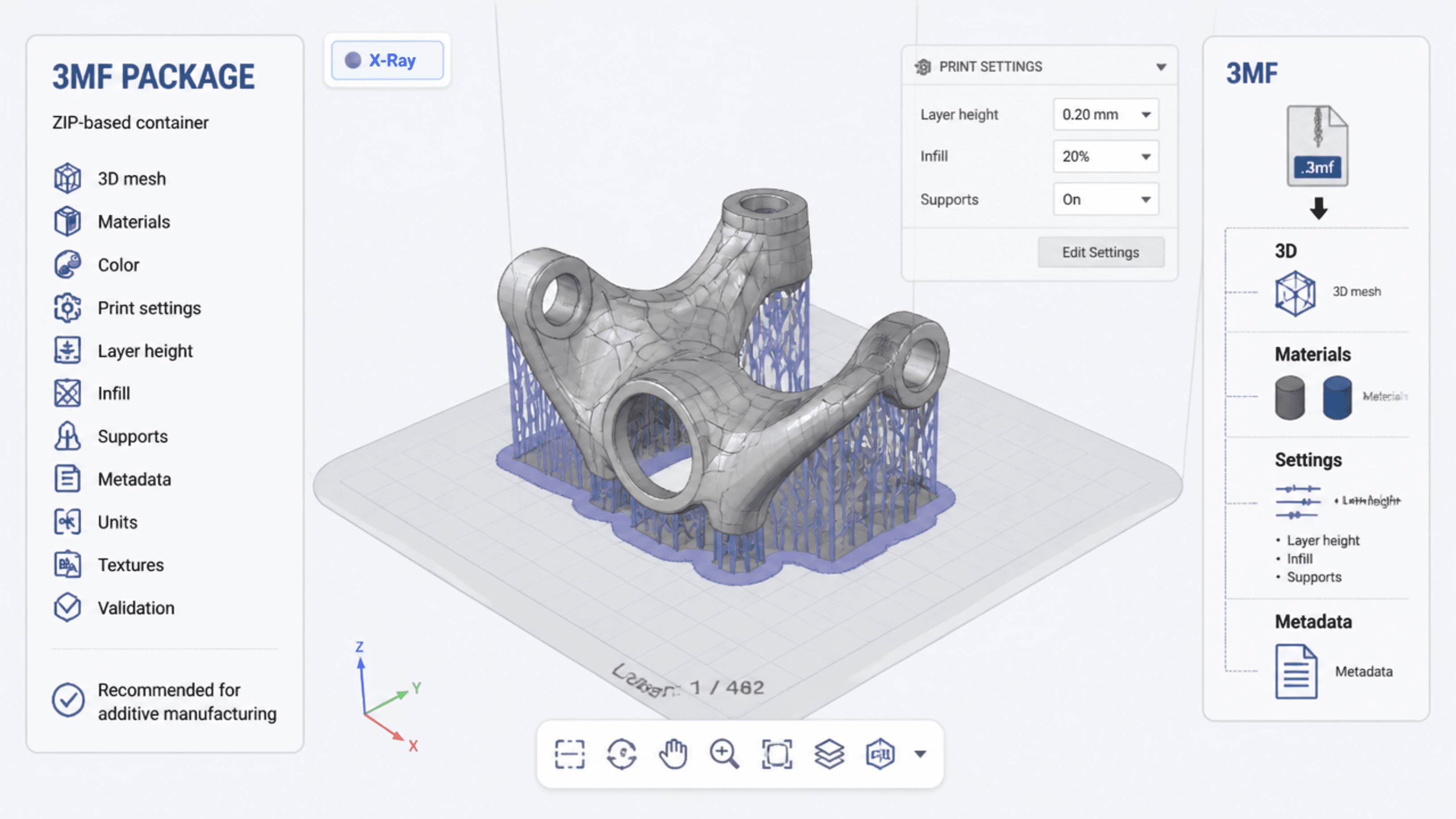
Not every 3MF contains all of this information.
The exact contents depend on the software that created the file, the 3MF features or extensions used, and any application-specific manufacturing data stored within the package.
Core Engineering Principle
A geometry warning should not automatically trigger a repair. Understand the finding, inspect the affected geometry and determine whether it represents an actual defect or intentional design geometry before modifying the model.
Engineering Validation
Detection is the beginning, not the end. Moksha3D identifies measurable geometry conditions. Where intervention is required, the geometry should be inspected and repaired appropriately, then re-analysed to establish whether the resulting model satisfies the required validation checks.
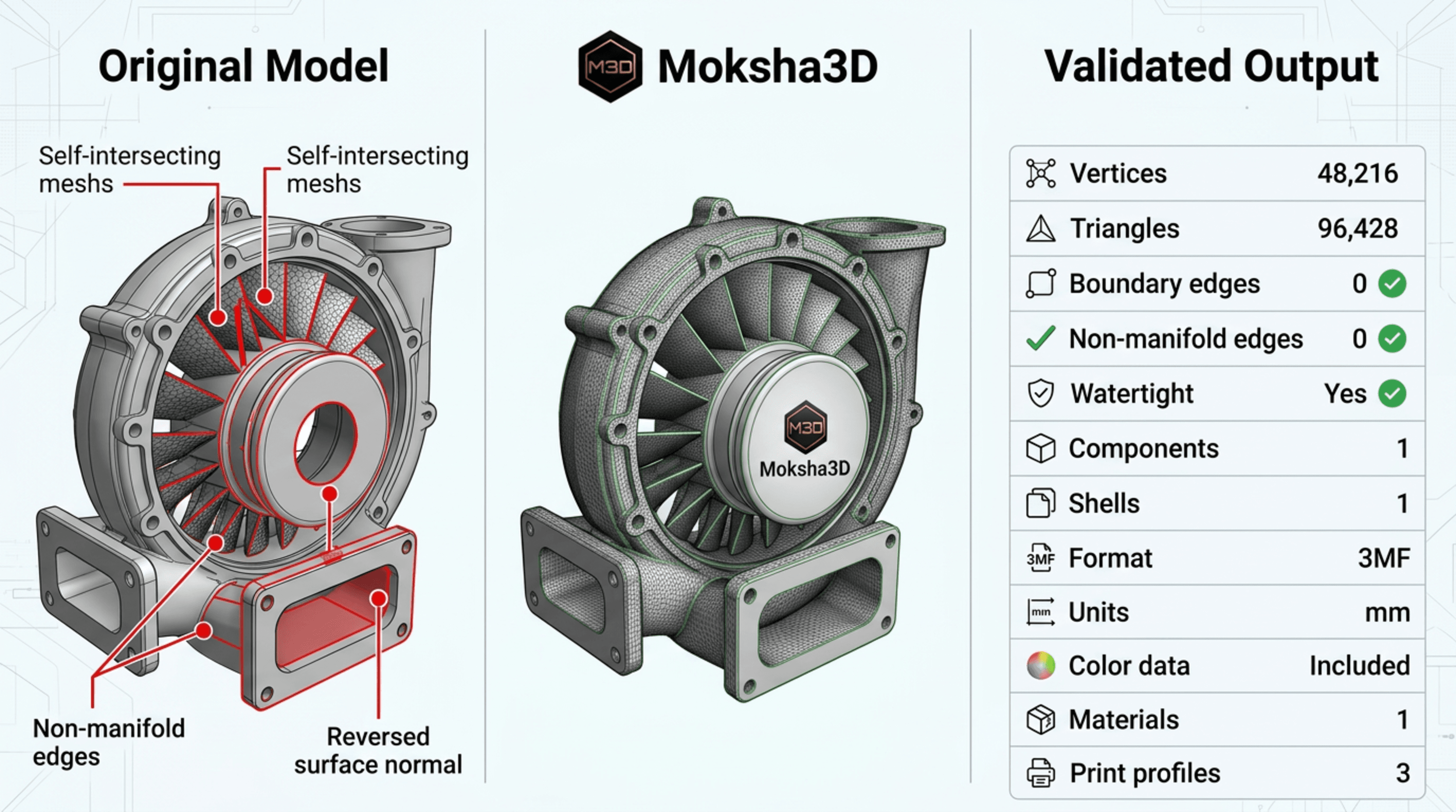
Illustrative engineering workflow. Values shown in the diagram are examples and do not represent analysis results for a specific uploaded model.
Moksha3D Workflow
STEP 1
Analyse
STEP 2
Interpret
STEP 3
Inspect
STEP 4
Repair
STEP 5
Re-analyse
STEP 6
Verify
Detect → understand → inspect → repair → re-analyse → verify.
3MF Knowledge Base
Work through the guide in sequence or open the section relevant to the finding you are investigating.
Understand what 3MF analysis can tell you, what it cannot prove, and how engineering findings should be interpreted.
Start with 3MF Analysis →Learn what vertices, triangles, boundaries, non-manifold conditions, watertightness, components and transforms mean.
Understand the Findings →What should you actually do when Moksha3D reports PASS, REPAIR REQUIRED or a condition that needs manual investigation?
Understand PASS / REPAIR →Understand open boundaries, non-manifold topology, disconnected components and other geometry conditions before attempting repair.
Understand Mesh Faults →Why Moksha3D, Blender, Meshmixer, MeshLab and other tools can report different numbers without one of them necessarily being wrong.
Compare Analysis Tools →Use Blender to locate reported geometry, inspect topology and make controlled manual repairs.
Open Blender Guide →Use Meshmixer Inspector to visually locate open boundaries, non-manifold regions and disconnected mesh problems.
Open Meshmixer Guide →Use MeshLab for independent mesh inspection, cleaning, non-manifold investigation and controlled repair.
Open MeshLab Guide →Verify the repaired model layer by layer and check that walls, holes, cavities, supports and printable regions remain correct.
Verify in a Slicer →Re-analyse the repaired model, compare the findings, confirm dimensions and decide whether the model is ready to use.
Post-Repair Validation →There is no single repair tool that is best for every mesh. The correct choice depends on the geometry, the type of fault and how much manual control you need.
Mesh analysis depends on definitions, tolerances, preprocessing and the way each application interprets topology. Blender, Meshmixer, MeshLab, slicers and Moksha3D can therefore describe the same model differently.
Compare what geometry each tool is identifying — not only the headline number.
Read the Analysis Tool Comparison →The objective is not simply to remove warnings. The objective is to understand the model, preserve the intended design, correct genuine geometry faults and verify that the final model behaves as expected before manufacturing.